What Product Types are Included in the Crane Resistor Wiring Diagram?
I. Introduction
Crane operations are integral to various industries, from construction to manufacturing, where heavy lifting and precise movements are essential. A critical component of these operations is the crane resistor wiring diagram, which serves as a blueprint for understanding how electrical components interact within the crane system. This article aims to explore the different product types included in crane resistor wiring diagrams, emphasizing their significance in ensuring safe and efficient crane operations.
II. Understanding Crane Resistor Wiring Diagrams
A. Explanation of Wiring Diagrams in General
Wiring diagrams are visual representations of electrical circuits, illustrating how components are interconnected. They provide essential information for installation, maintenance, and troubleshooting, allowing technicians to understand the flow of electricity and the relationships between various parts of a system.
B. Specifics of Crane Resistor Wiring Diagrams
1. Functionality of Resistors in Cranes
In crane systems, resistors play a vital role in controlling the speed and torque of electric motors. They help manage the electrical current flowing to the motors, ensuring smooth operation and preventing damage due to excessive current. Resistors can be used in various configurations, depending on the specific requirements of the crane.
2. Role of Wiring Diagrams in Maintenance and Troubleshooting
Wiring diagrams are indispensable tools for maintenance personnel. They provide a clear understanding of the electrical layout, enabling technicians to identify issues quickly and accurately. By following the wiring diagram, technicians can trace faults, replace components, and ensure that the crane operates safely and efficiently.
III. Types of Cranes and Their Resistor Wiring Needs
A. Overhead Cranes
1. Description and Common Applications
Overhead cranes are widely used in warehouses, manufacturing plants, and construction sites. They consist of a hoist that moves along a horizontal beam, allowing for the lifting and transporting of heavy loads.
2. Resistor Types Used
In overhead cranes, dynamic resistors are commonly employed to control the speed of the hoist motor. These resistors dissipate excess energy as heat, allowing for smooth acceleration and deceleration.
B. Gantry Cranes
1. Overview and Typical Uses
Gantry cranes are similar to overhead cranes but are supported by legs that move on wheels or tracks. They are often used in shipyards, rail yards, and construction sites for lifting heavy materials.
2. Resistor Configurations
Gantry cranes may utilize both dynamic and static resistors, depending on the application. Static resistors are often used in conjunction with contactors to manage the starting and stopping of the crane's motors.
C. Jib Cranes
1. Characteristics and Applications
Jib cranes are smaller, more versatile cranes that can rotate 360 degrees. They are commonly used in workshops and manufacturing facilities for lifting lighter loads.
2. Resistor Requirements
Jib cranes typically require simpler resistor configurations, often using static resistors to control the motor's starting current and prevent sudden jolts.
D. Mobile Cranes
1. Definition and Operational Contexts
Mobile cranes are versatile machines that can be moved from one location to another. They are used in various applications, including construction, demolition, and heavy lifting.
2. Resistor Wiring Considerations
Mobile cranes often incorporate advanced control systems, requiring complex resistor wiring diagrams. These diagrams must account for the various functions of the crane, including boom extension, rotation, and lifting.
IV. Key Components in Crane Resistor Wiring Diagrams
A. Resistors
1. Types of Resistors (e.g., Dynamic, Static)
Resistors in crane systems can be classified into dynamic and static types. Dynamic resistors are used for speed control, while static resistors are typically employed for starting current management.
2. Specifications and Ratings
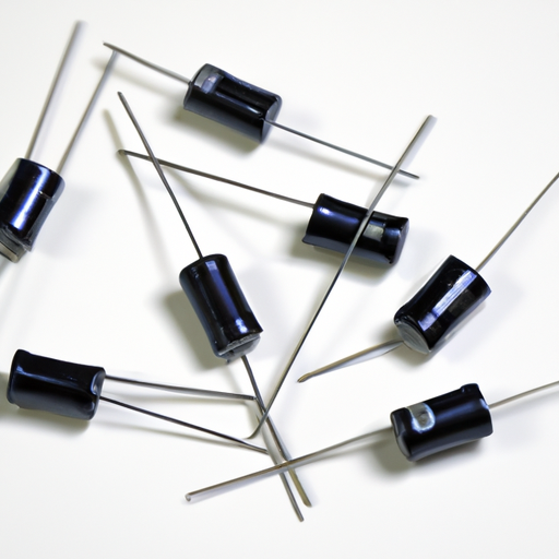
Each resistor type has specific ratings, including resistance value, power rating, and tolerance. Understanding these specifications is crucial for selecting the appropriate resistor for a given application.
B. Contactors
1. Role in Crane Operations
Contactors are electrically controlled switches that manage the flow of electricity to the crane's motors. They play a critical role in starting and stopping the motors safely.
2. Wiring Connections with Resistors
In wiring diagrams, contactors are often shown in conjunction with resistors, illustrating how they work together to control motor operation.
C. Relays
1. Functionality in Control Circuits
Relays are electromagnetic switches that control the flow of electricity in a circuit. They are used to manage various functions within the crane, such as safety features and operational controls.
2. Integration with Resistors
Relays are often integrated with resistors in wiring diagrams, showing how they work together to ensure safe and efficient crane operation.
D. Power Supply Units
1. Importance in Crane Systems
Power supply units provide the necessary electrical energy for crane operations. They convert incoming electrical power into a usable form for the crane's components.
2. Wiring Interactions with Resistors
Wiring diagrams illustrate how power supply units connect with resistors and other components, ensuring that the crane receives the correct voltage and current.
E. Control Panels
1. Overview of Control Systems
Control panels are the central hub for managing crane operations. They house various controls, indicators, and safety features that allow operators to monitor and control the crane.
2. Wiring Diagram Implications
Wiring diagrams for control panels show how various components, including resistors, contactors, and relays, are interconnected, providing a comprehensive view of the crane's electrical system.
V. Common Wiring Configurations
A. Series vs. Parallel Configurations
1. Definitions and Differences
In series configurations, components are connected end-to-end, meaning the same current flows through each component. In contrast, parallel configurations allow multiple paths for current to flow, providing redundancy and reliability.
2. Applications in Crane Systems
Crane systems may utilize both series and parallel configurations, depending on the specific requirements of the application. Understanding these configurations is essential for designing effective wiring diagrams.
B. Safety Features in Wiring Diagrams
1. Fuses and Circuit Breakers
Fuses and circuit breakers are critical safety components in crane wiring diagrams. They protect the electrical system from overloads and short circuits, ensuring safe operation.
2. Emergency Stop Systems
Emergency stop systems are essential for ensuring operator safety. Wiring diagrams must clearly indicate how these systems are integrated into the overall electrical layout.
VI. Importance of Accurate Wiring Diagrams
A. Safety Considerations
1. Risks of Incorrect Wiring
Incorrect wiring can lead to severe safety hazards, including electrical fires, equipment damage, and personal injury. Accurate wiring diagrams are crucial for preventing these risks.
2. Importance of Compliance with Standards
Compliance with industry standards and regulations is essential for ensuring the safety and reliability of crane operations. Wiring diagrams must adhere to these standards to minimize risks.
B. Maintenance and Troubleshooting
1. Role of Diagrams in Identifying Issues
Accurate wiring diagrams are invaluable for maintenance personnel, allowing them to quickly identify and resolve issues within the crane's electrical system.
2. Benefits of Having Accurate Diagrams for Repairs
Having up-to-date wiring diagrams simplifies the repair process, reducing downtime and ensuring that the crane remains operational.
VII. Conclusion
Understanding crane resistor wiring diagrams is essential for anyone involved in crane operations, maintenance, or design. These diagrams provide critical insights into the various product types and their interactions within the crane's electrical system. By recognizing the importance of accurate wiring diagrams, operators and technicians can ensure safe and efficient crane operations, ultimately contributing to the success of their projects.
As the industry continues to evolve, further learning and consultation with experts will be vital for staying informed about best practices and advancements in crane technology. Embracing this knowledge will not only enhance operational efficiency but also promote a culture of safety and reliability in crane operations.
VIII. References
- Suggested readings and resources for further information on crane operations and wiring diagrams.
- Industry standards and guidelines related to crane operations and electrical systems.

