What are the Product Features of Resistor Diagrams?
I. Introduction
In the world of electronics, understanding the components that make up circuits is crucial for both beginners and seasoned professionals. One of the fundamental components is the resistor, and a resistor diagram serves as a vital tool for visualizing how these components interact within a circuit. A resistor diagram is a graphical representation that illustrates the arrangement and values of resistors in an electronic circuit. This article aims to explore the importance of resistor diagrams, their key features, and how they can be effectively utilized in both educational and professional settings.
II. Overview of Resistors
A. What is a Resistor?
A resistor is a passive electronic component that limits the flow of electric current in a circuit. Its primary function is to provide resistance, which is measured in ohms (Ω). Resistors are essential for controlling voltage and current levels, ensuring that other components in the circuit operate within their specified limits.
1. Function and Purpose
The primary purpose of a resistor is to manage the flow of current. By doing so, it protects sensitive components from excessive current that could lead to damage. Resistors are also used to divide voltages, create specific current paths, and condition signals for processing.
2. Types of Resistors
There are several types of resistors, including fixed resistors, variable resistors (potentiometers), and specialized resistors like thermistors and photoresistors. Each type serves a unique purpose and is chosen based on the specific requirements of the circuit.
B. Role of Resistors in Circuits
Resistors play a critical role in various circuit functions:
1. Current Limiting
In many applications, resistors are used to limit the amount of current flowing through a circuit. This is particularly important in protecting components like LEDs, which can be damaged by excessive current.
2. Voltage Division
Resistors can be arranged in series to create a voltage divider, allowing designers to obtain a specific voltage from a higher voltage source. This is useful in applications where different components require different operating voltages.
3. Signal Conditioning
In signal processing, resistors are used to filter and shape signals. They can help in adjusting the gain of amplifiers and in creating specific frequency responses in audio circuits.
III. Key Features of Resistor Diagrams
A. Visual Representation
One of the most significant features of resistor diagrams is their ability to provide a clear visual representation of a circuit.
1. Symbols and Notations
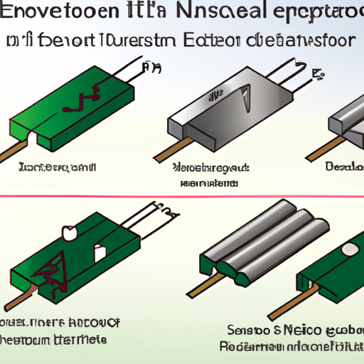
Resistor diagrams utilize standardized symbols to represent resistors, making it easier for engineers and technicians to understand the circuit's layout. The most common symbol for a resistor is a zigzag line, but variations exist for different types of resistors.
2. Circuit Layout
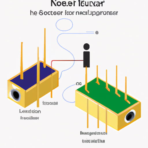
A well-designed resistor diagram will clearly show how resistors are connected within the circuit, whether in series, parallel, or a combination of both. This layout is crucial for understanding the overall function of the circuit.
B. Component Identification
Resistor diagrams also facilitate the identification of various components within a circuit.
1. Resistor Values
Each resistor in a diagram is typically labeled with its resistance value, allowing for quick identification and analysis. This is essential for troubleshooting and circuit design.
2. Tolerance and Power Ratings
In addition to resistance values, diagrams often include information about the tolerance and power ratings of resistors. This information is vital for ensuring that the components used in a circuit can handle the expected electrical load.
C. Connection Types
Resistor diagrams illustrate the different ways resistors can be connected in a circuit.
1. Series and Parallel Configurations
Understanding whether resistors are connected in series or parallel is crucial for calculating total resistance and analyzing circuit behavior. Diagrams clearly indicate these configurations, making it easier to perform necessary calculations.
2. Node Representation
Diagrams also represent nodes, which are points where two or more components connect. This representation is essential for understanding how current flows through the circuit.
IV. Detailed Elements of Resistor Diagrams
A. Resistor Symbols
1. Standard Symbols
The standard symbol for a resistor is a zigzag line, but there are variations for different types of resistors, such as variable resistors and potentiometers. Understanding these symbols is essential for reading and interpreting diagrams accurately.
2. Variations for Different Types
Different types of resistors may have unique symbols. For example, a variable resistor is often represented by a similar zigzag line with an arrow indicating its adjustable nature. Familiarity with these variations is crucial for accurate circuit analysis.
B. Color Coding
1. Understanding Resistor Color Codes
Resistors often have color bands that indicate their resistance value, tolerance, and sometimes temperature coefficient. Understanding these color codes is essential for interpreting resistor values quickly.
2. Importance in Diagrams
In resistor diagrams, color coding can be referenced to provide additional information about the resistors used. This can be particularly helpful in educational settings where students are learning to read and interpret diagrams.
C. Annotations and Labels
1. Value Indications
Annotations in resistor diagrams typically include the resistance value, tolerance, and power rating. These labels provide essential information for anyone working with the circuit.
2. Additional Information
Diagrams may also include additional information, such as the temperature coefficient of resistors, which can affect their performance in varying conditions. This information is crucial for ensuring the reliability of the circuit.
V. Software and Tools for Creating Resistor Diagrams
A. Popular Software Options
Creating resistor diagrams has become easier with the advent of various software tools.
1. Circuit Design Software
Programs like Eagle, KiCad, and Altium Designer are popular among professionals for designing complex circuits. These tools offer extensive libraries of components, including resistors, and allow for precise layout and simulation.
2. Online Diagram Tools
For simpler projects, online tools like Lucidchart and CircuitLab provide user-friendly interfaces for creating resistor diagrams without the need for extensive software installation.
B. Features of Diagramming Tools
1. Drag-and-Drop Functionality
Many diagramming tools offer drag-and-drop functionality, making it easy to add components and create circuits quickly.
2. Predefined Templates
Templates can save time and ensure consistency in design. Many software options provide templates for common circuit configurations, including those involving resistors.
3. Export and Sharing Options
Once a diagram is complete, it can often be exported in various formats (PDF, PNG, etc.) for sharing or printing. This feature is essential for collaboration and documentation.
VI. Applications of Resistor Diagrams
A. Educational Use
1. Teaching Electronics Concepts
Resistor diagrams are invaluable in educational settings, helping students visualize and understand complex electronic concepts. They serve as a foundation for learning about circuit design and analysis.
2. Lab Exercises
In laboratory settings, students can use resistor diagrams to build and test circuits, reinforcing their understanding of how resistors function within a circuit.
B. Professional Use
1. Circuit Design and Prototyping
Professionals use resistor diagrams extensively in circuit design and prototyping. These diagrams help engineers communicate their designs clearly and ensure that all components are correctly specified.
2. Documentation and Communication
In professional environments, resistor diagrams serve as documentation for circuits, making it easier for teams to collaborate and for future engineers to understand existing designs.
VII. Best Practices for Creating Resistor Diagrams
A. Clarity and Readability
1. Use of Colors and Fonts
Using distinct colors and fonts can enhance the readability of resistor diagrams. Clear labeling and contrasting colors help ensure that important information stands out.
2. Avoiding Clutter
A cluttered diagram can lead to confusion. It's essential to keep diagrams simple and focused, avoiding unnecessary details that could distract from the main components.
B. Consistency in Symbols and Notations
Maintaining consistency in symbols and notations across diagrams is crucial for clarity. This consistency helps users quickly understand the information presented without having to decipher different styles.
C. Regular Updates and Revisions
As circuits evolve, so should their diagrams. Regularly updating and revising resistor diagrams ensures that they remain accurate and useful for anyone referencing them.
VIII. Conclusion
In conclusion, resistor diagrams are an essential tool in the field of electronics, providing a clear and concise way to represent the role of resistors in circuits. Their importance cannot be overstated, as they facilitate understanding, communication, and collaboration among engineers, students, and hobbyists alike. As technology continues to advance, the tools and methods for creating these diagrams will also evolve, offering even more opportunities for learning and innovation. Whether you are a student just starting or a professional looking to refine your skills, mastering the art of reading and creating resistor diagrams is a valuable endeavor that will enhance your understanding of electronics and circuit design.


